- 您现在的位置:买卖IC网 > Sheet目录221 > DPM35G (Martel Electronics)METER DPM LED 3.5DIGIT GREEN
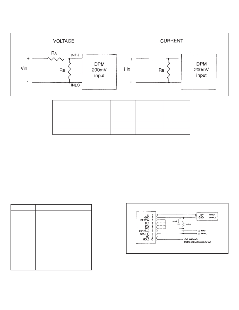
Ranging DPMs for Voltage & Current
VIN
2V
20V
200V
1000V*
RA**
1 Meg
1 Meg
1 Meg
10 Meg***
RB**
110 k
10 k
1k
1k
I in
2 mA
20 mA
200 mA
RB**
100
10
1
*
When attentuating voltages above 20V care must be used to use components rated for higher voltages and that
proper creepage and clearance distances are used. Refer to UL3111 or IEC 1010.
** Resistors should be 1%, 1/4 wattt with a 100 or 50 ppm temperature coefficient (Note: Recalibration of span
required if accuracy better than ±1.4% is desired.)
*** Use (2) 4.99 Meg in series if 10 Meg is not available.
Connection Descriptions
Wiring Connections
PIN
V+
GND
DP COM
DP1
DP2
DP3
Input (+)
Input (–)
Description
+5V DPM Power Supply
DPM Power Supply Ground
Decimal Point Return
1XX.X
1X.XX
1.XXX
Positive Input Signal
Negative Input Signal
NC
HOLD
No Connection Required
Hold Last Display
The input common mode range is ± 1Vdc. If INPUT (–) is not
directly conected to GND, a 10k resistor network can be connect-
ed as shown to reduce unstable readings.
Unused pins should be left open.
CAUTION: Damage to the unit can occur if the power source
polarity is reversed, or greater than 6V is applied
between pins 1 & 2.
DPM-35
发布紧急采购,3分钟左右您将得到回复。
相关PDF资料
DPM3AS-BL
LCD 11MM UNIV MINI METER BK LIT
DPM500SBL
METER DPM LCD 3.5DIGIT
DPM65S
METER DPM LCD SINGLE RAIL 200MV
DPM702S
PANEL METER LCD DL 200MV 3.5 DGT
DPM742-BL
PANEL METER LCD 4-20MA W/BK LITE
DPM750S-BL
PANEL METER LCD 200MV 3.5 DIGIT
DPM942
3.5 DIGIT 4-20MA LOOP POWERED
DPM950S
3.5 DIGIT 200MVDC LED BACKLIT
相关代理商/技术参数
DPM35R
功能描述:METER DPM LED 3.5DIGIT RED RoHS:是 类别:工业控制,仪表 >> 仪表 - 面板,数字 系列:35/65 标准包装:12 系列:* 其它名称:Q7072030
DPM3A11C9B
制造商:OSLO SWITCH 功能描述:
DPM3A12C9B
制造商:OSLO SWITCH 功能描述:
DPM3AS-BL
功能描述:LCD 11MM UNIV MINI METER BK LIT RoHS:是 类别:工业控制,仪表 >> 仪表 - 面板,数字 系列:10 标准包装:12 系列:* 其它名称:Q7072030
DPM3S
制造商:未知厂家 制造商全称:未知厂家 功能描述:The DPM 3 is the largest in our sub-miniature series of meters but still uses the same miniaturisation techniques to produce a very compact instrument
DPM40
功能描述:METER DPM LED 3.5DIGIT 200MV IN RoHS:是 类别:工业控制,仪表 >> 仪表 - 面板,数字 系列:- 标准包装:12 系列:* 其它名称:Q7072030
DPM40-2
功能描述:METER DPM LED 3.5 DIGIT 2V IN RoHS:是 类别:工业控制,仪表 >> 仪表 - 面板,数字 系列:- 标准包装:12 系列:* 其它名称:Q7072030
DPM40-20
功能描述:METER DPM LED 3.5DIGIT 20V IN RoHS:否 类别:工业控制,仪表 >> 仪表 - 面板,数字 系列:- 标准包装:12 系列:* 其它名称:Q7072030
